zoul: Zolertia Zoul platforms: Firefly, RE-mote and Orion
Zoul Platforms
Zolertia Zoul Module
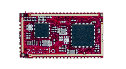
The Zoul is a core module developed by Zolertia to target most IoT applications, providing a flexible and affordable module solution to integrate to most existing products and solutions, or ease the prototyping and production of new products in a short time.
The Zoul is based on TI’s CC2538 system on chip (SoC), featuring an ARM Cortex-M3 with 512KB flash, 32Kb RAM, double RF interface, and the following goodies:
ISM 2.4-GHz IEEE 802.15.4 & Zigbee compliant.
ISM 868-, 915-, 920-, 950-MHz ISM/SRD Band.
AES-128/256, SHA2 Hardware Encryption Engine.
ECC-128/256, RSA Hardware Acceleration Engine for Secure Key Exchange.
Small form-factor of 16.78 x 30.89 mm.
Prototype friendly, to fit on most prototyping boards (breadboard, etc.).
Self-contained and EMI-protected module under a shield.
The Zoul will be CE/FCC certified (2016) to allow a fast integration and short time to market for new products and solutions.
Zoul pin-out

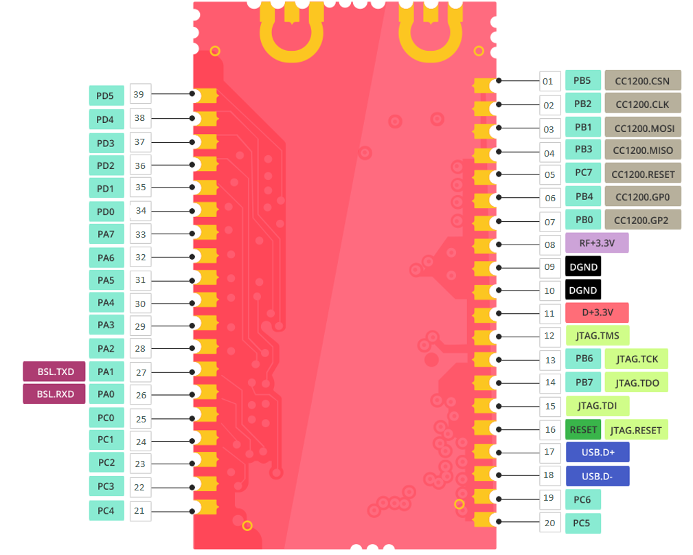
Port Features
The Zoul has the following key features:
Deep Sleep support with RAM retention for ultra-low energy consumption.
Native USB support (CDC-ACM). SLIP over UART for border routers is no longer a bottleneck.
DMA transfers for increased performance (RAM to/from RF, RAM to/from USB).
In terms of hardware support, the following drivers have been implemented for the Zoul-based platforms:
CC2538 System-on-Chip:
Standard Cortex M3 peripherals (NVIC, SCB, SysTick)
Sleep Timer (underpins rtimers)
SysTick (underpins the platform clock and Contiki-NG’s timers infrastructure)
RF (2.4GHz)
UART
Watchdog (in watchdog mode)
USB (in CDC-ACM)
uDMA Controller (RAM to/from USB and RAM to/from RF)
Random number generator
Low Power Modes
General-Purpose Timers. NB: GPT0 is in use by the platform code, the remaining GPTs are available for application development.
ADC
Cryptoprocessor (AES-ECB/CBC/CTR/CBC-MAC/GCM/CCM-128/192/256, SHA-256)
Public Key Accelerator (ECDH, ECDSA)
Flash-based port of Coffee
PWM
LEDs
Buttons
Built-in core temperature and battery sensor.
CC1200 sub-1GHz radio interface.
Real Time Clock Calendar (on the RE-Mote platform).
SD
There is a Zoul powering the RE-Mote and Firefly platforms, check out its specific README files for more information about on-board features.
Requirements
To start using Contiki-NG, the following is required:
A zoul-based board (RE-Mote, firefly)
A toolchain to compile Contiki-NG for the CC2538.
Drivers so that your OS can communicate with your hardware.
Software to upload images to the CC2538.
Toolchain Installation
The toolchain used to build Contiki-NG is arm-gcc, also used by other arm-based Contiki-NG ports.
If you use the docker image or the vagrant image, this will be pre-installed for you. Otherwise, depending on your system, please follow the respective installation instructions (native Linux / native mac OS).
Drivers
Depending on your Zoul flavour, there are different options. As today the RE-Mote and Firefly platforms host a Zoul with a CP2104 USB-to-serial converter, governed by a low-power PIC to handle resetting and flashing the Zoul over USB, without having to press any button or use external tools.
The driver is available at https://www.silabs.com/products/mcu/Pages/USBtoUARTBridgeVCPDrivers.aspx
Check the board’s specific Wiki page for more information.
For windows users, if using the USB 2.0 interface (via CDC-ACM driver), there is an available driver in this folder:
zolertia-zoul-cdc-acm
Software to Program the Nodes
The Zoul can be programmed via the jtag interface or via the serial boot loader on the chip.
Both the RE-Mote and Firefly has a mini JTAG 10-pin male header, compatible with the SmartRF06 development board, which can be used to flash and debug the platforms. Alternatively one could use the JLink programmer with a 20-to-10 pin converter like the following: https://www.olimex.com/Products/ARM/JTAG/ARM-JTAG-20-10/.
The serial boot loader on the chip is exposed to the user via an USB interface. In the not so distant past we used to press a button sequence to unlock the boot loader, but now an on-board PIC in both RE-Motes and Fireflies handles this on its own, so it will detect the BSL sequence and flash the CC2538 without user intervention.
Instructions to flash for different OS are given below.
On Windows:
Nodes can be programmed with TI’s ArmProgConsole or the SmartRF Flash Programmer 2. The README should be self-explanatory. With ArmProgConsole, upload the file with a
.binextension. (jtag + serial)Nodes can also be programmed via the serial boot loader in the cc2538. In
tools/cc2538-bsl/you can findcc2538-bsl.pythis is a python script that can download firmware to your node via a serial connection. If you use this option you just need to make sure you have a working version of python installed. You can read the README in the same directory for more info. (serial)
On Linux:
Nodes can be programmed with TI’s UniFlash tool. With UniFlash, use the file with
.elfextension. (jtag + serial)Nodes can also be programmed via the serial boot loader in the cc2538. No extra software needs to be installed. (serial)
On OSX:
The
cc2538-bsl.pyscript intools/cc2538-bsl/is the only option. No extra software needs to be installed. (serial)
The file with a .zoul extension is a copy of the .elf file.
Build your First Examples
For a review of make targets and in particular the selection of TARGET and BOARD, see doc:build-system.
You can try the examples under examples/platform-specific/zoul.
If you want to upload the compiled firmware to a node via the serial boot loader you need first to either manually enable the boot loader, or just let the Co-Processor detect the flash sequence and do it on your behalf, as simple as not pressing anything at all!
Then use, e.g., make test-motion.upload.
The PORT argument could be used to specify in which port the device is connected, in case we have multiple devices connected at the same time.
To enable printing debug output to your console, use the make login to get the information over the USB programming/debugging port, or alternatively use make serialview to also add a timestamp in each print.
Node IEEE and IPv6 Addresses
Nodes will generally autoconfigure their IPv6 address based on their IEEE address. The IEEE address can be read directly from the CC2538 Info Page, or it can be hard-coded. Additionally, the user may specify a 2-byte value at build time, which will be used as the IEEE address’ 2 LSBs.
To configure the IEEE address source location (Info Page or hard-coded), use the IEEE_ADDR_CONF_HARDCODED define in contiki-conf.h:
0: Info Page
1: Hard-coded
If IEEE_ADDR_CONF_HARDCODED is defined as 1, the IEEE address will take its value from the IEEE_ADDR_CONF_ADDRESS define. If IEEE_ADDR_CONF_HARDCODED is defined as 0, the IEEE address can come from either the primary or secondary location in the Info Page. To use the secondary address, define IEEE_ADDR_CONF_USE_SECONDARY_LOCATION as 1.
Additionally, you can override the IEEE’s 2 LSBs, by using the NODEID make variable. The value of NODEID will become the value of the IEEE_ADDR_NODE_ID pre-processor define. If NODEID is not defined, IEEE_ADDR_NODE_ID will not get defined either. For example:
make NODEID=0x79ab
This will result in the 2 last bytes of the IEEE address getting set to 0x79 0xAB
Note: Some early production devices do not have am IEEE address written on the Info Page. If your device is in this category, define IEEE_ADDR_CONF_HARDCODED to 1 and specify NODEID to differentiate between devices.
Low-Power Modes
The CC2538 port supports power modes for low energy consumption. The SoC will enter a low power mode as part of the main loop when there are no more events to service.
LPM support can be disabled in its entirety by setting LPM_CONF_ENABLE to 0 in contiki-conf.h or project-conf.h.
The Low-Power module uses a simple heuristic to determine the best power mode, depending on anticipated Deep Sleep duration and the state of various peripherals.
In a nutshell, the algorithm first answers the following questions:
Is the RF off?
Are all registered peripherals permitting PM1+?
Is the Sleep Timer scheduled to fire an interrupt?
If the answer to any of the above question is “No”, the SoC will enter PM0. If the answer to all questions is “Yes”, the SoC will enter one of PMs 0/1/2 depending on the expected Deep Sleep duration and subject to user configuration and application requirements.
At runtime, the application may enable/disable some Power Modes by making calls to lpm_set_max_pm(). For example, to avoid PM2 an application could call lpm_set_max_pm(1). Subsequently, to re-enable PM2 the application would call lpm_set_max_pm(2).
The LPM module can be configured with a hard maximum permitted power mode.
#define LPM_CONF_MAX_PM N
Where N corresponds to the PM number. Supported values are 0, 1, 2. PM3 is not supported. Thus, if the value of the define is 1, the SoC will only ever enter PMs 0 or 1 but never 2 and so on.
The configuration directive LPM_CONF_MAX_PM sets a hard upper boundary. For instance, if LPM_CONF_MAX_PM is defined as 1, calls to lpm_set_max_pm() can only enable/disable PM1. In this scenario, PM2 can not be enabled at runtime.
When setting LPM_CONF_MAX_PM to 0 or 1, the entire SRAM will be available. Crucially, when value 2 is used the linker will automatically stop using the SoC’s SRAM non-retention area, resulting in a total available RAM of 16kB instead of 32kB.
Shutdown Mode
The RE-Mote has a built-in shutdown mode which effectively reduces the power consumption down to 150nA. Check its specific README file for more information.
Build headless nodes
It is possible to turn off all character I/O for nodes not connected to a PC. Doing this will entirely disable the UART as well as the USB controller, preserving energy in the long term. The define used to achieve this is (1: Quiet, 0: Normal output):
#define CC2538_CONF_QUIET 0
Setting this define to 1 will automatically set the following to 0:
USB_SERIAL_CONF_ENABLEUART_CONF_ENABLESTARTUP_CONF_VERBOSE
Code Size Optimizations
The build system currently uses optimization level -Os, which is controlled indirectly through the value of the SMALL make variable. This value can be overridden by example makefiles, or it can be changed directly in platform/zoul/Makefile.zoul.
Historically, the -Os flag has caused problems with some toolchains. If you are using one of the toolchains documented in this README, you should be able to use it without issues. If for whatever reason you do come across problems, try setting SMALL=0 or replacing -Os with -O2 in cpu/cc2538/Makefile.cc2538.
More Reading
Maintainers
The Zoul and derived platforms (as well as the Z1 mote) are maintained by Zolertia. Main contributor: Antonio Lignan alinan@zolertia.com antonio.lignan@gmail.com